

Technical Column
Differences Between Free-Field, Pressure-Field, and Random-Incidence Microphones: How to Choose and Use Them for Your Measurement Space
Sep 30, 2026
- HBK × SONORA Acoustic Measurement Solution Official Website
- Technical Column
- Differences Between Free-Field, Pressure-Field, and Random-Incidence Microphones: How to Choose and Use Them for Your Measurement Space
Acoustic Power Measurement

Introduction
When looking through a catalog of measurement microphones, you will find many models with the same 1/2-inch size, similar appearance, and comparable sensitivity. However, next to the model numbers, you will see designations such as “Free-field,” “Pressure,” or “Random incidence (Diffuse-field).” If you choose the wrong type, errors of several decibels can occur at higher frequencies.
These classifications do not indicate superior or inferior microphone performance. Rather, they represent a design assumption regarding which sound field the microphone is optimized for to achieve a flat frequency response. In other words, selecting a microphone is inextricably linked to “where you are measuring.”
This article clarifies the differences between the three types of measurement condenser microphones, explains how to choose the right one for various measurement environments (such as anechoic chambers, reverberation rooms, and couplers), and highlights common pitfalls in the field.
Why Do Characteristics Change According to “Type”?
When a microphone is placed in a sound field, the microphone itself acts as an obstacle to the sound. At low frequencies, the wavelength is much longer than the microphone dimensions, so its presence has almost no effect. However, as the frequency increases and the wavelength approaches the physical size of the microphone, reflection and diffraction occur in front of the diaphragm, causing a local rise in sound pressure.
The outer diameter of a 1/2-inch microphone is approximately 12.7 mm. Assuming a speed of sound in air of about 343 m/s, the frequency at which the wavelength equals 12.7 mm is roughly 27 kHz. In practice, the influence begins to appear at a few kilohertz and increases toward higher frequencies. This pressure increase also varies depending on the angle of incidence of the sound.
Therefore, manufacturers optimize microphones to achieve a flat response in one of three sound fields. As described in HBK’s (Brüel & Kjær) Microphone Handbook, sound fields for acoustic measurement are divided into free-field, pressure-field, and diffuse-field, with microphones designed to yield a flat frequency response in their respective target fields.
Differences Among the Three Types
| Type | Assumed Sound Field | What It Is Designed to Measure | Microphone Orientation | Typical Applications |
|---|---|---|---|---|
| Free-field Type | Reflection-free environment where sound arrives from a single direction | The sound pressure that existed at that location before placing the microphone | Pointed directly at the sound source (0° incidence) | Measurements in anechoic/semi-anechoic chambers, outdoor noise, loudspeaker testing |
| Pressure-field Type | Sound field with uniform amplitude and phase regardless of position | The actual sound pressure exerted directly on the diaphragm surface | Flush-mounted into walls or couplers | Couplers, artificial ears, boundary surfaces, wind tunnels, enclosed cavities |
| Random Incidence Type (Diffuse-field) | Sound arrives with equal probability from all directions | The average sound pressure integrated over all directions of incidence | Orientation independent | Reverberation rooms, vehicle interiors, aircraft cabins, highly reflective rooms |
Free-Field Microphones
A free-field microphone is designed by anticipating the high-frequency pressure rise caused by its own presence, tuning its sensitivity so that it achieves a flat response at 0° incidence (pointing at the source). Since its output corresponds to “the sound pressure before the microphone was introduced,” it is widely used in free-field measurements such as speaker testing in anechoic chambers.
Conversely, correct orientation is a prerequisite for free-field microphones. They only deliver their designed characteristics when pointed directly at the sound source.
Pressure-Field Microphones
Pressure-field microphones are designed to measure the actual sound pressure acting directly on the surface of the diaphragm with a flat response. This applies to setups where the microphone diaphragm becomes part of a coupler wall or test surface—such as in artificial ears for earphone testing (IEC 60318 series) or flush-mounted measurements on aircraft/vehicle bodies.
When using a pressure-field microphone in a different sound field, its high-frequency response will not be flat out of the box. In such cases, sound field corrections provided for the specific microphone model must be applied.
Random-Incidence Microphones
In environments like reverberation rooms or vehicle cabins where sound arrives simultaneously from all directions, sound coming from the front increases the pressure, while sound coming from behind is shielded by the microphone body. Random-incidence microphones are engineered so that their statistically averaged response over all directions is flat.
Standardized incidence distributions govern how this average is calculated. In the HBK handbook, random-incidence corrections are calculated according to IEC 61183 by measuring free-field corrections at 5° increments.
According to the HBK handbook, pressure-field microphones can also be used in diffuse fields in addition to coupler measurements, as the response of a pressure-field microphone is relatively close to that of a random-incidence microphone.
Identifying Types via Designation Standard — IEC 61094-4
The IEC 61094-4 standard for working standard microphones specifies microphone designations as follows:
- WS1 / WS2 / WS3: Size classification (approx. 1-inch / 1/2-inch / 1/4-inch)
- Suffix F / P / D: Optimized sound field (Free-field / Pressure / Diffuse)
For example, the calibration certificate of an HBK 1/2-inch free-field microphone will state “WS2F.” If you are unsure of your microphone type, checking this designation on the calibration certificate is the most reliable method.
Selection Guide by Measurement Environment
| Measurement Environment / Application | Recommended Type | Notes |
|---|---|---|
| Anechoic / semi-anechoic chamber testing | Free-field | Point directly at source. Consider low-noise microphones if ambient noise is very low. |
| Frequency response & directivity of speakers/alarms | Free-field | On-axis (0°) measurement is standard. |
| Reverberation room testing | Random incidence | HBK also allows pressure-field microphones in diffuse fields. |
| Vehicle interiors, aircraft cabins, highly reflective rooms | Random incidence | For fields where sound arrival direction is undefined. |
| Couplers for earphones/hearing aids, artificial ears, HATS ears | Pressure-field | Measures sound pressure inside closed small cavities. |
| Flush-mounting on walls, fuselage surfaces, or in wind tunnels | Pressure-field (surface microphone) | Microphone becomes part of the surface boundary. |
| Outdoor environmental noise (sound level meters) | Free-field | Follow sound level meter design standards and specifications. |
This table serves as a general guideline based on sound field characteristics. When performing measurements according to standards such as sound power determination, always check the relevant standard text and instrument manuals for specific requirements on microphone type, orientation, and instrument performance.
When Used in Small Anechoic Enclosures
In compact testing enclosures like anechoic boxes, the distance between the DUT and microphone is short, and sound may not arrive from a single defined direction. Selection depends on whether you are conducting absolute measurements per standards or comparative pass/fail testing. For comparative testing, keeping microphone type, position, and orientation identical across tests is far more critical than strict absolute accuracy.
Sound Level Meter Standards: “IEC” vs. “ANSI”
Part of the confusion surrounding microphone types stems from the history of sound level meter standards.
Historically, IEC standards for sound level meters referenced free-field response, whereas the older US ANSI S1.4 standard referenced random-incidence response. In fact, older HBK free-field microphones could be fitted with a random-incidence corrector to comply with ANSI requirements.
In 2014, ANSI/ASA S1.4-2014 Part 1 adopted IEC 61672-1:2013 identically, harmonizing sound level meter standards globally. However, IEC 61672-1 accounts for designs suitable for sound arriving from a single free-field direction as well as random directions. Consequently, US test standards or customer specifications may still require random-incidence or pressure-field microphones. It is essential to check local standards and customer internal regulations.
Common Pitfalls in the Field
1. Not Pointing Free-Field Microphones at the Sound Source
A common mistake is pointing a sound level meter straight up on a tripod while measuring machinery off to the side. With a free-field microphone, this orientation error alone causes high-frequency measurement errors. If sound arrives from multiple sources, re-evaluating whether a free-field microphone is appropriate is necessary.
2. Overlooking Differences Between Calibrator Values and Free-Field Sensitivity
Acoustic calibrators and pistonphones apply a known sound pressure inside a closed coupler cavity where the microphone is inserted. Sensitivity obtained in a coupler does not always perfectly match free-field sensitivity.
The magnitude of this difference depends on the microphone model and calibration frequency. In HBK’s handbook, for a specific 1/2-inch free-field microphone at 1 kHz, free-field sensitivity is 0.15 dB higher than pressure sensitivity, so calibrator settings should be adjusted 0.15 dB lower. Conversely, for models calibrated at 250 Hz, the stated sensitivity is often valid across free-field, random-incidence, and pressure-field applications.
While the difference may seem small, for precision measurements and uncertainty calculations, it is worthwhile to verify correction handling in calibration certificates and instrument settings.
3. Accessories Altering High-Frequency Response
Accessories such as protection grids, random-incidence correctors, and windscreens all alter high-frequency response. HBK provides correction data for different sound fields and grid configurations, allowing analysis software to apply appropriate corrections. Always check which accessories were attached when calibration certificate data was obtained.
4. Smaller Microphones Do Not Solve Every Problem
1/4-inch and 1/8-inch microphones have small dimensions, pushing the frequency where sound field effects occur higher and reducing differences between microphone types. However, smaller microphones have lower sensitivity and higher self-noise. For measuring quiet sound sources in low-noise anechoic chambers, 1/2-inch or larger low-noise microphones may be required (Related: Low-Noise Microphones for Use in Anechoic Chambers and Boxes).
Summary
- Differences between free-field, pressure-field, and random-incidence types reflect design assumptions regarding which sound field yields a flat frequency response, not performance quality.
- Differences manifest at higher frequencies where wavelengths approach microphone dimensions.
- Use free-field microphones pointed at the source in anechoic/semi-anechoic chambers. Use random-incidence microphones in reverberation rooms or vehicle interiors, and pressure-field microphones in couplers or on surfaces.
- Microphone designations can be confirmed via IEC 61094-4 codes (WS2F / WS2P / WS2D, etc.).
- Slight differences may exist between calibrator coupler sensitivity and free-field sensitivity depending on model and frequency; check calibration certificates for guidance.
Selecting a microphone type is also a judgment on what type of sound field exists within your measurement space. A free-field microphone performs as designed only when an anechoic room functions properly, just as random-incidence assumptions hold when a reverberation room is sufficiently diffuse. At Moritani, we propose HBK measurement microphones and SONORA anechoic chambers/boxes as an integrated measurement system where spatial acoustic conditions and microphone types align perfectly.
Related Articles
- Low-Noise Microphones for Use in Anechoic Chambers and Boxes
- How to Use HATS ― Operating a Measurement System That Reproduces the Human Head and Ears Within the Framework of Standards and Acoustic Environments ―
- Reverberation Chamber/Reverberation Box
- Mapping the Directionality of Acoustic Devices — Directivity Measurement with HBK Microphones, Turntable, and AEB —
- Misconceptions About a Sound Absorption Coefficient of 0.99 ― How ISO 3745:2012 Changed the Philosophy of Anechoic Room Evaluation ―
- Cable Noise During Acoustic Measurements
References
- Brüel & Kjær, Microphone Handbook for the Falcon™ Range of Microphone Products (BE 1373-12) https://www.bksv.com/media/doc/be1373.pdf
- Brüel & Kjær, Product Data: ½″ Prepolarized Free-field Microphone Type 4189 https://www.bksv.com/-/media/literature/Product-Data/bp2210.ashx
- ANSI/ASA S1.4-2014/Part 1 / IEC 61672-1:2013 (Electroacoustics – Sound level meters – Part 1: Specifications) https://webstore.ansi.org/preview-pages/ASA/preview_ANSI+ASA+S1.4-2014+Part+1+IEC+61672-1-2013+(R2019).pdf
- IEC 61094-4 (Measurement microphones – Part 4: Specifications for working standard microphones)
- IEC 61183 (Electroacoustics – Random-incidence and diffuse-field calibration of sound level meters)
- IEC 60318 series (Electroacoustics – Simulators of human head and ear)
Latest Posts in Technical Column
-
2026.09.30
Differences Between Free-Field, Pressure-Field, and Random-Incidence Microphones: How to Choose and Use Them for Your Measurement Space -
2026.08.03
Why Are Anechoic Chamber Walls Spiky? How Acoustic Wedges Work -
2026.07.28
White Noise vs Pink Noise vs Sweep Signals -
2026.07.13
Acoustic Adjustment with Soundproof Partitions ― Applications for Anechoic Chamber Tuning, Simplified Acoustic Measurements, and STI Environment Design ― -
2026.07.08
Why HBK × SONORA? ― The Benefits of Integrating Acoustic Instrumentation and Acoustic Test Environments ― -

2026.05.18
Misconceptions About a Sound Absorption Coefficient of 0.99 ― How ISO 3745:2012 Changed the Philosophy of Anechoic Room Evaluation ― -
2026.05.13
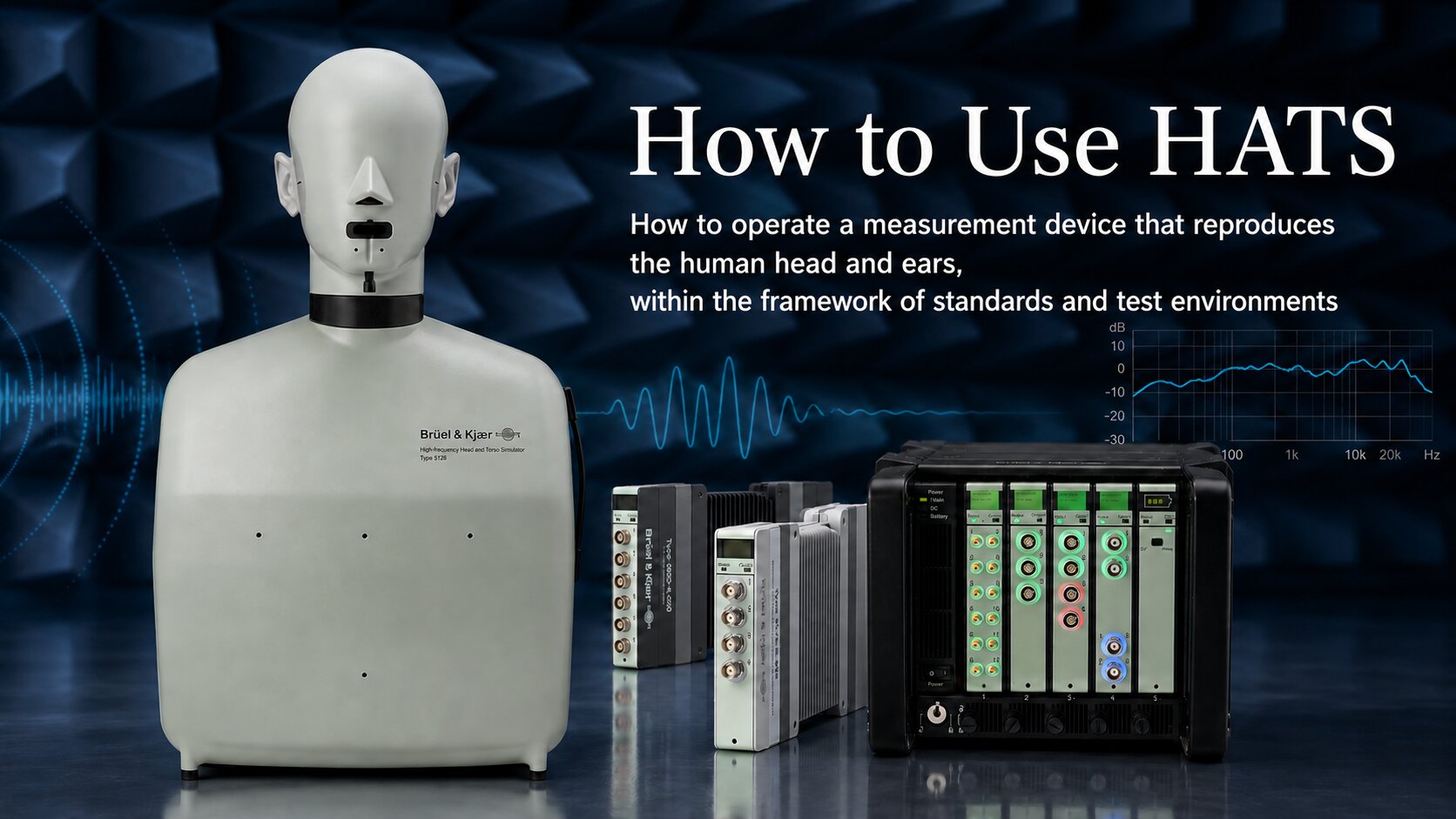
How to Use HATS ― Operating a Measurement System That Reproduces the Human Head and Ears Within the Framework of Standards and Acoustic Environments ― -
2026.04.13
Evaluation Methods in Building Acoustics: Streamlining Field Measurements and Material Assessment in Laboratory Environments -

2026.03.23
We participated in the corporate exhibition at the Acoustical Society of Japan (ASJ) Meeting on March 19, 2026 -
2026.03.10
How to Read Standards Related to Anechoic Chambers ― Organizing Sound Power Measurement Standards and Qualification of Test Environments ―

Contact Us
- Contact us by email
-
- Contact us by phone
-
Moritani Shokai
(Machinery Department No. 2, Tokyo Head Office)


Introduction of the Manufacturer
-

Hottinger Bruel & Kjaer
HHBK is a merger of two companies: Brüel & Kjær of Denmark and HBM of Germany.
Brüel & Kjær is one of the world’s leading manufacturers of acoustic and vibration measurement instruments, known as a total measurement chain supplier.Learn more about HBK
-
Sonora Technology Co., Ltd.
Sonora Technology is a leading Japanese manufacturer of industrial anechoic chambers and anechoic boxes.
From design and manufacturing to installation and acoustic performance assurance, Sonora provides fully integrated solutions to build complete acoustic measurement environments from the ground up.Learn more about Sonora
Contact / Request Brochure
For inquiries or consultations regarding the total solutions provided by HBK × Sonora, please feel free to contact us using the Contact button.
If you would like a brochure sent by mail, please use the Request Brochure button.