

Technical Column
Why Are Anechoic Chamber Walls Spiky? How Acoustic Wedges Work
Aug 3, 2026
- HBK × SONORA Acoustic Measurement Solution Official Website
- Technical Column
- Why Are Anechoic Chamber Walls Spiky? How Acoustic Wedges Work
Acoustic Power Measurement
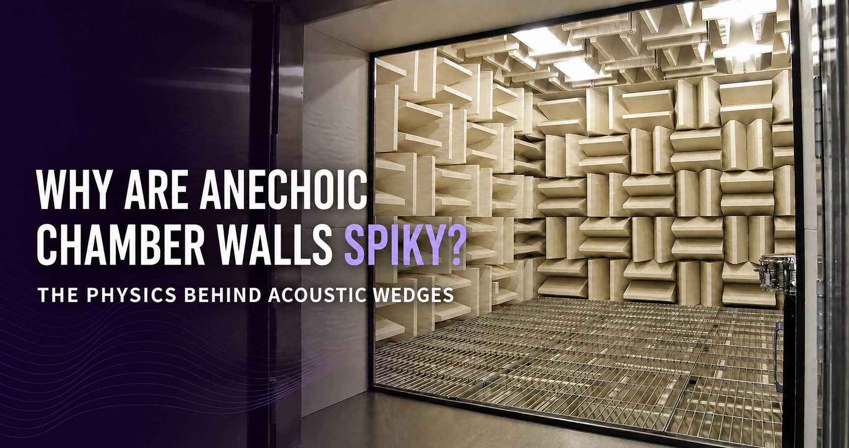
Why Are Anechoic Chamber Walls “Spiky”? The Physics Behind Acoustic Wedges
Walk into an anechoic chamber and one feature immediately stands out: the walls and ceiling are covered with rows of pointed absorbers. These are generally known as acoustic wedges or sound-absorbing wedges.
At first glance, a flat layer of the same material might seem more practical. It would be easier to manufacture and would leave more usable space inside the chamber. Yet wedge-shaped absorbers have been used in conventional anechoic chambers for decades because their geometry offers clear acoustic advantages.
In simple terms, the tapered shape creates a more gradual transition between air and the absorbing material. This helps reduce reflection at the front of the absorber and allows more sound energy to enter the material. The wedge also provides the depth needed to control progressively lower frequencies.
That does not mean a chamber must have pointed wedges to be anechoic. Flat and hybrid absorber systems can also create suitable free-field conditions when they are correctly designed for the target frequency range, chamber size, durability requirements, and measurement standard.
How Porous Absorbers Dissipate Sound
Acoustic wedges are commonly made from porous materials such as glass wool or other fibrous absorbers.
Inside a porous absorber is a network of narrow passages filled with air. When a sound wave enters the material, the air in these passages oscillates. The movement is resisted by viscosity near the internal surfaces, while repeated compression and expansion also produces small thermal exchanges between the air and the material.
Through these viscous and thermal losses, part of the acoustic energy is converted into a minute amount of heat.
Porous absorption is sometimes described simply as “friction between the air and the fibers.” That explanation is useful at an introductory level, but the actual mechanism includes both viscous and thermal effects.
Flat Absorbers Can Still Absorb Sound
A flat layer of glass wool can provide substantial sound absorption. With appropriate thickness, density, airflow resistivity, facing material, and backing air space, a flat absorber can achieve high performance.
So why use a wedge?
One reason is the reflection that occurs where air meets the absorbing structure.
Acoustic impedance describes the relationship between sound pressure and particle velocity. It plays an important role when a sound wave passes from one acoustic region into another. Because air and a porous absorber have different effective acoustic properties, not all of the incident sound enters a flat absorber; some of it is reflected at the surface.
To make full use of the absorbing material, the design should allow as much sound energy as possible to enter it.
A Wedge Creates a More Gradual Acoustic Transition
An acoustic wedge is narrow at the tip and becomes progressively wider toward its base.
This does not mean that the material itself becomes denser from tip to base. If the wedge is made from one material, its material density is essentially constant. What changes is the proportion of absorber occupying the space encountered by the incoming wave.
Near the tip, only a small part of the wavefront meets absorbing material. Farther into the wedge array, the proportion of absorber gradually increases. The effective acoustic properties therefore change more smoothly from open air to an absorber-dominated region.
The wedge does not eliminate the boundary completely. Instead, it replaces an abrupt transition with a gradual one—rather like replacing a step with a ramp.
This geometry helps reduce reflection near the entrance and encourages sound to propagate farther into the porous material, where viscous and thermal losses can dissipate its energy. The depth of the wedge also provides a substantial absorption path, which is particularly important at lower frequencies.
Acoustic Wedge Performance Depends on More Than Shape
The visible profile is only one part of an acoustic wedge design. Performance is influenced by several interacting factors:
| Design factor | Main influence |
|---|---|
| Wedge length and width | Usable frequency range and available chamber volume |
| Tip and base geometry | Front-face reflection, strength, and manufacturability |
| Material density and airflow resistivity | How readily sound enters the material and how strongly it is dissipated |
| Facing material | Acoustic transparency, durability, cleanability, and fiber control |
| Backing air space | Absorption characteristics, especially at lower frequencies |
| Angle of incidence | Reflection and absorption under practical sound-field conditions |
| Chamber geometry and absorber arrangement | Free-field performance of the completed room |
Low-frequency sound has a long wavelength, so controlling it generally requires greater absorber depth.
For example, if the speed of sound is taken as approximately 343 m/s, the wavelength at 100 Hz is about 3.43 m. One quarter of that wavelength is approximately 0.86 m.
The quarter-wavelength rule has long been used as a practical design guideline when estimating absorber depth. It should not, however, be treated as an absolute requirement for every wedge. Actual performance also depends on airflow resistivity, material density, wedge geometry, backing air space, facing material, and angle of incidence.
For more detail on low-frequency performance and absorber design, see:
- Lower Limit Frequency for Measurements in an Anechoic Chamber
- The Truth Behind the 0.99 Absorption Coefficient: Understanding Cut-off Frequency and the Performance of Acoustic Wedges
Does Every Anechoic Chamber Need Acoustic Wedges?
No. Acoustic wedges are a well-established solution for reducing reflections, but they are not the only possible absorber system.
Modern facilities may use flat porous absorbers, multilayer systems, absorbers with backing cavities, or hybrid structures that combine several absorption mechanisms. The best approach depends on:
- the frequency range to be measured;
- the required free-field performance;
- the usable internal dimensions;
- the size of the test object;
- source and microphone positions;
- durability, cleanability, and fire performance;
- the possibility of future modification or relocation; and
- project cost.
The performance of an anechoic chamber cannot be judged simply by whether its walls look “spiky.” The decisive question is whether the required free-field conditions are achieved within the specified frequency range and measurement region.
Related discussions are available in Misconceptions About a Sound Absorption Coefficient of 0.99 and The Geometry of Acoustic Design.
Beranek and Sleeper’s 1946 Study
An important early reference in the development of anechoic chamber absorbers is the 1946 paper by L. L. Beranek and H. P. Sleeper, Jr.
The researchers compared five absorber constructions for use in anechoic chambers. Among the designs tested, a wedge made from bonded glass fiber produced the best result. The paper also presented a method of designing the wedge around either the desired minimum frequency or the maximum absorber depth that could be accommodated in the room.
The two completed chambers described in the paper were also evaluated through measurements based on inverse-square-law behavior.
The paper should not be described as definitive proof that Beranek invented the acoustic wedge. It is more accurately regarded as one of the landmark studies that systematized the design and evaluation of wedge absorbers for anechoic chambers.
Absorber Performance and the Chamber’s Qualified Lower Frequency Are Different
The performance of an individual absorber and the performance of a completed anechoic chamber must be considered separately.
A normal-incidence absorption coefficient evaluates a sample under a defined test condition, with sound arriving perpendicular to the specimen. It is valuable for comparing and designing materials or absorber structures, but it does not by itself establish the free-field performance of an entire chamber.
The completed sound field is also affected by the room dimensions, absorber arrangement, source and microphone positions, floor construction, doors, lighting, HVAC systems, penetrations, and test fixtures.
ISO 26101-1:2021 specifies methods for qualifying anechoic and hemi-anechoic environments as completed acoustic spaces. Absorber test data should therefore be used to support absorber design, while the chamber’s usable frequency range and measurement region should be confirmed by sound-field measurements after installation.
For additional guidance, see How to Read Standards Related to Anechoic Chambers.
Frequently Asked Questions
Can an anechoic chamber be built with flat absorbers?
Yes. Flat absorber systems can be used if their thickness, backing air space, arrangement, and other design parameters are appropriate for the target frequency range and room dimensions. The completed chamber must then be shown to provide the required free-field performance.
Does a longer acoustic wedge always perform better?
Greater depth generally makes it easier to control lower frequencies, but length alone does not determine performance. Airflow resistivity, density, geometry, facing material, backing air space, and installation arrangement must also be considered.
Must the tip of an acoustic wedge be perfectly sharp?
No. A truncated tip can still provide the required performance when the material, dimensions, and layout are properly designed. The shape must be evaluated as part of the complete absorber system rather than by appearance alone.
Do ISO standards require the use of wedge-shaped absorbers?
No single wedge shape is universally mandated. What matters is whether the test environment satisfies the free-field requirements of the applicable measurement and qualification standards.
Are “cut-off frequency” and “qualified lower frequency” the same?
Not exactly. Cut-off frequency is commonly used when discussing the performance of an absorber or absorber system. The qualified lower frequency refers to the lowest frequency at which the completed chamber meets the required acoustic-field criteria for its intended use. The latter must be established through measurements of the finished facility.
Summary
The walls of an anechoic chamber are not wedge-shaped merely to increase the exposed surface area. Acoustic wedges are used because they can:
- create a more gradual acoustic transition from air into the absorber;
- reduce reflection near the entrance and help sound enter the porous material;
- provide the depth needed for effective absorption; and
- support the formation of the free-field region required for acoustic measurement.
Wedge geometry alone does not determine chamber performance. Material properties, absorber dimensions, backing cavities, chamber geometry, frequency range, source and microphone positions, and reflections from installed equipment must be designed as one system. The completed chamber must then be qualified by acoustic-field measurements.
Moritani Shokai combines HBK acoustic and vibration measurement systems with Sonora Technology’s anechoic chambers, hemi-anechoic chambers, and anechoic enclosures, supporting customers from system configuration and implementation through operation.
For product information, see Sonora Technology’s New Sound-Absorbing Wedge “BFW”. The benefits of considering the measurement system and acoustic environment together are explained in Why HBK × SONORA?.
To arrange a demonstration or view acoustic measurement facilities, visit Showroom & Demonstration. For support with a new or upgraded chamber, measurement-system selection, or standards compliance, please contact Moritani Shokai.
References
- L. L. Beranek and H. P. Sleeper, Jr., “The Design and Construction of Anechoic Sound Chambers,” The Journal of the Acoustical Society of America, Vol. 18, No. 1, pp. 140–150, 1946. DOI: 10.1121/1.1916351
- Mark J. Cops et al., “Estimation of Acoustic Absorption in Porous Materials Based on Visco-Thermal Boundary Layers Modeled as Boundary Conditions,” The Journal of the Acoustical Society of America, Vol. 148, pp. 1624–1635, 2020. DOI: 10.1121/10.0001959
- ISO 26101-1:2021, Acoustics — Test methods for the qualification of acoustic environments — Part 1: Qualification of free-field environments
- ISO 10534-2:2023, Acoustics — Determination of acoustic properties in impedance tubes — Part 2: Two-microphone technique for normal sound absorption coefficient and normal surface impedance
Latest Posts in Technical Column
-
2026.08.03
Why Are Anechoic Chamber Walls Spiky? How Acoustic Wedges Work -
2026.07.28
White Noise vs Pink Noise vs Sweep Signals -
2026.07.13
Acoustic Adjustment with Soundproof Partitions ― Applications for Anechoic Chamber Tuning, Simplified Acoustic Measurements, and STI Environment Design ― -
2026.07.08
Why HBK × SONORA? ― The Benefits of Integrating Acoustic Instrumentation and Acoustic Test Environments ― -

2026.05.18
Misconceptions About a Sound Absorption Coefficient of 0.99 ― How ISO 3745:2012 Changed the Philosophy of Anechoic Room Evaluation ― -
2026.05.13
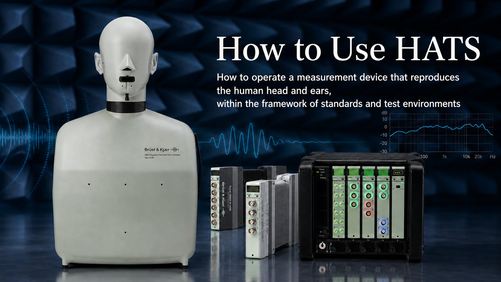
How to Use HATS ― Operating a Measurement System That Reproduces the Human Head and Ears Within the Framework of Standards and Acoustic Environments ― -
2026.04.13
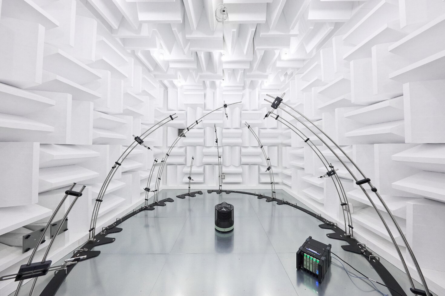
Evaluation Methods in Building Acoustics: Streamlining Field Measurements and Material Assessment in Laboratory Environments -

2026.03.23
We participated in the corporate exhibition at the Acoustical Society of Japan (ASJ) Meeting on March 19, 2026 -
2026.03.10
How to Read Standards Related to Anechoic Chambers ― Organizing Sound Power Measurement Standards and Qualification of Test Environments ― -
2026.01.29
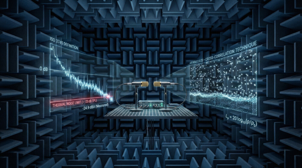
Can We Create “Absolute Silence” on Earth? — An Academic Reading of Anechoic Chambers and Ultra-Low Background-Noise Measurement —

Contact Us
- Contact us by email
-
- Contact us by phone
-
Moritani Shokai
(Machinery Department No. 2, Tokyo Head Office)


Introduction of the Manufacturer
-

Hottinger Bruel & Kjaer
HHBK is a merger of two companies: Brüel & Kjær of Denmark and HBM of Germany.
Brüel & Kjær is one of the world’s leading manufacturers of acoustic and vibration measurement instruments, known as a total measurement chain supplier.Learn more about HBK
-
Sonora Technology Co., Ltd.
Sonora Technology is a leading Japanese manufacturer of industrial anechoic chambers and anechoic boxes.
From design and manufacturing to installation and acoustic performance assurance, Sonora provides fully integrated solutions to build complete acoustic measurement environments from the ground up.Learn more about Sonora
Contact / Request Brochure
For inquiries or consultations regarding the total solutions provided by HBK × Sonora, please feel free to contact us using the Contact button.
If you would like a brochure sent by mail, please use the Request Brochure button.